
EECIT Kits User Manuals
-
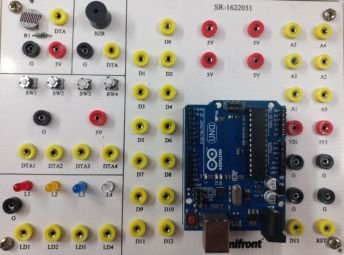 Ardiuno BoardContains: LDR, 4 LEDs, 4 Push Buttons, and a Buzzer.
-
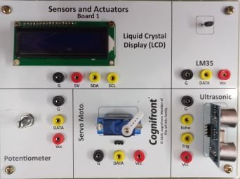 Sensor Actuator Board 1Contains: I2C LCD 16x2, LM35 Temperature Sensor, HC-SR04 Ultrasonic Sensor, Servo Motor, and a Potentiometer.
-
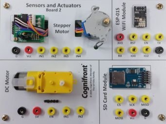 Sensor Actuator Board 2Contains: Stepper Motor with Driver, DC Motor with Driver, ESP-01S WiFi Module, and SD Card Module.


Objectives
- To INTRODUCE students to microcontroller programming and interfacing with digital and analog components.
- To EQUIP students with skills for data acquisition and processing from various sensors (temperature, distance, etc.).
- To TEACH students motor control techniques using microcontrollers for precise actuation and automation.
- To ENABLE students to design and implement integrated systems that demonstrate real-world automation applications.
Experiments With Arduino
- Experiment 1: Introduction to Arduino and Digital I/O Control
- Experiment 2: Analog Sensor Interfacing (Temperature Sensor -LM35)
- Experiment 3: Interfacing Potentiometer for Position Control Simulation
- Experiment 4: Interfacing IR or Ultrasonic Sensor for Distance Measurement
- Experiment 5: Controlling DC Motor Using Transistor Driver Circuit
- Experiment 6: Data Logging Using Arduino and Excel (Serial Communication)
- Experiment 7: Stepper Motor Control via Microcontroller
Experiments With ESP32
- Experiment 1: Introduction to ESP32 and Digital I/O Control
- Experiment 2: Analog Sensor Interfacing (Temperature Sensor -LM35) with ESP32
- Experiment 3: Interfacing Potentiometer for Position Control Simulation with ESP32
- Experiment 4: Interfacing IR or Ultrasonic Sensor for Distance Measurement with ESP32
- Experiment 5: Controlling DC Motor Using Transistor Driver Circuit using ESP32
- Experiment 6: Data Logging Using ESP32 and Excel (Cloud Communication)
- Experiment 7: Stepper Motor Control via Microcontroller ESP32
Experiments Mapping with board
📄 Download Experiments Mapping (PDF)